7 pin trailer wiring diagram usa Trailer wiring diagram plug way dump Wiring Diagram ID
A 7 pin connector is a simple device that has 3 more functions than the 4 pin version. Not only does it handle the same tasks as the 4 pin- running lights, left turn signal and brake lights, right turn signal and brake lights, and ground, it comes with the ability to run the trailer's 12-volt system, reverse lights and electric brake.. That is how the 7 pin connector got its name.

Wiring Diagram For A Trailer Connector
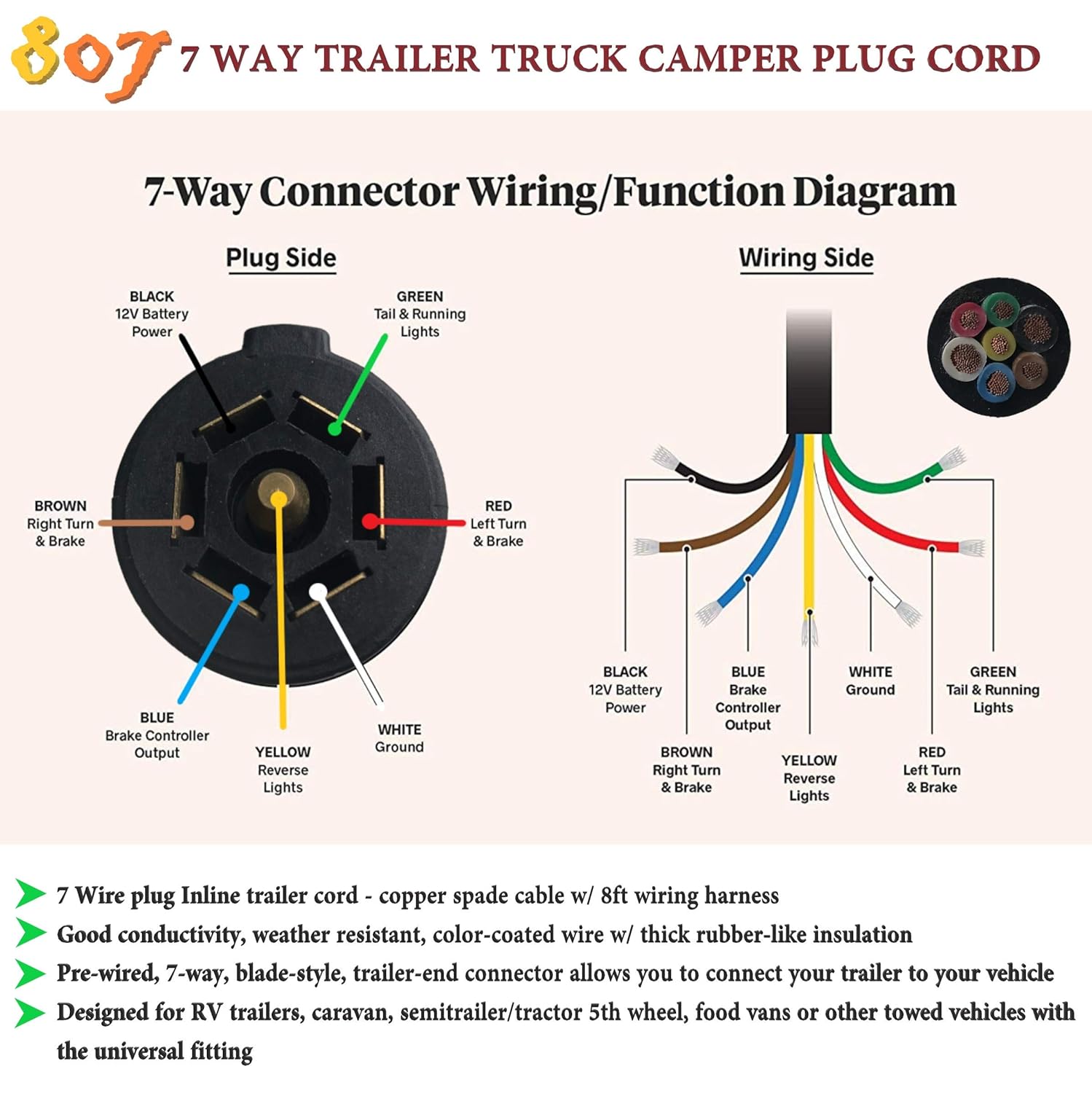
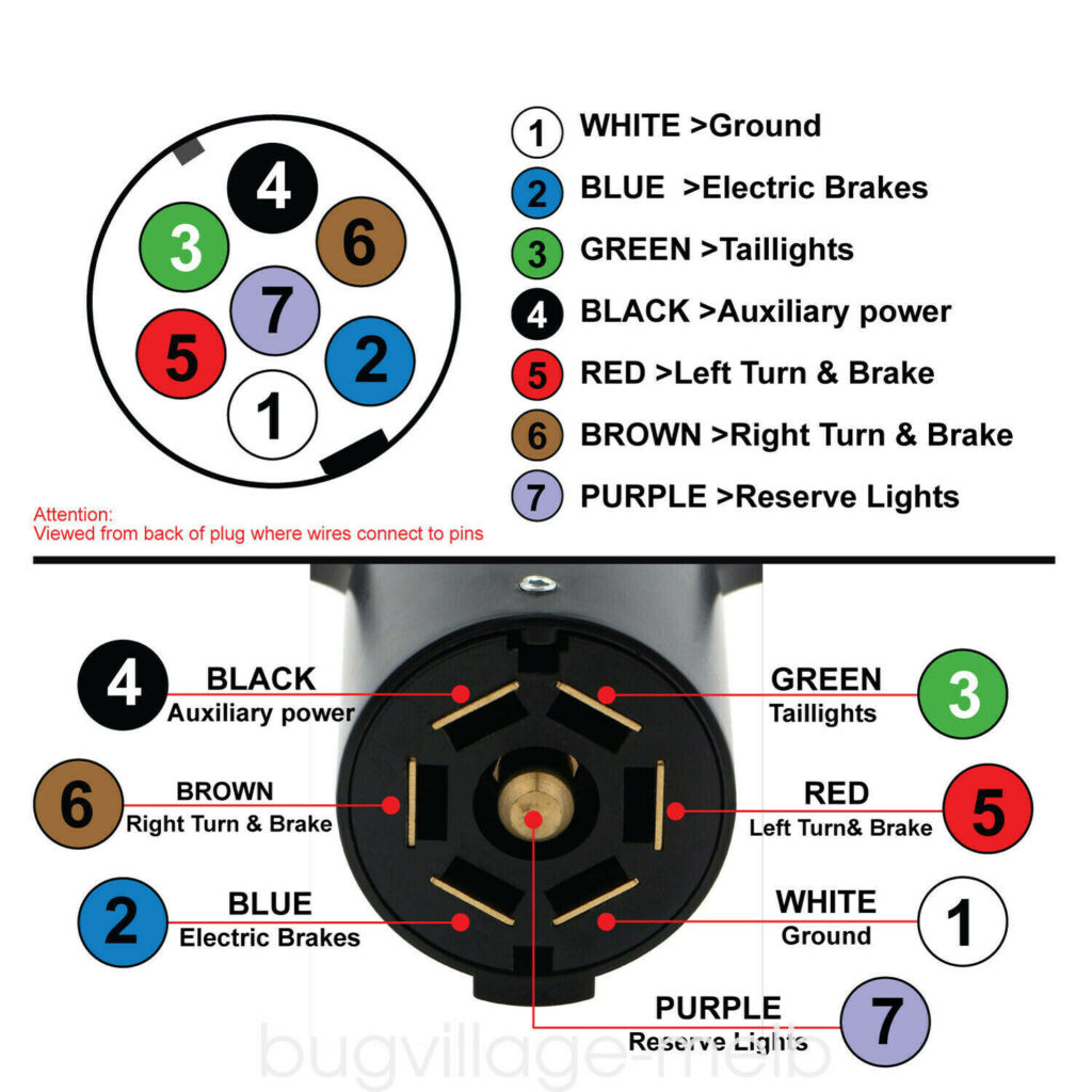
It is important to understand the purpose of each wire and the color coding associated with it. Here is an overview of the 7-pin plug: Pin 1: Auxiliary or Reverse Lights. Pin 2: Brake Lights. Pin 3: Right Turn Signal. Pin 4: Left Turn Signal. Pin 5: Ground. Pin 6: Electric Brakes. Pin 7: Battery/Charging.
Wiring A 7 Pin Trailer
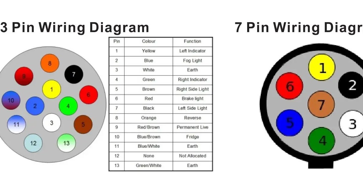
A 7 pin trailer wiring diagram is a schematic that shows the pinout and function of each wire in a 7-way round trailer connector. The standard 7-pin connector contains the following wires and functions: Pin 1 - Left Turn/Stop Signal (Green) Pin 2 - Ground (White) Pin 3 - Right Turn/Stop Signal (Yellow) Pin 4 - Auxiliary Power (Red)

7 Pin Connector Wiring
The 7 pin round trailer wiring diagram shows a connection between the trailer plug and the trailer wiring. This diagram usually comes with the trailer. It is the most common type of connection used for trailers. The diagram shows the color-coded wires that are used to connect the trailer plug to the trailer wiring. The 7 pin connector consists.
7 Pin Connector Wiring Diagram Wiring Diagram
How to wire a 7 pin trailer plug (diagram shown)

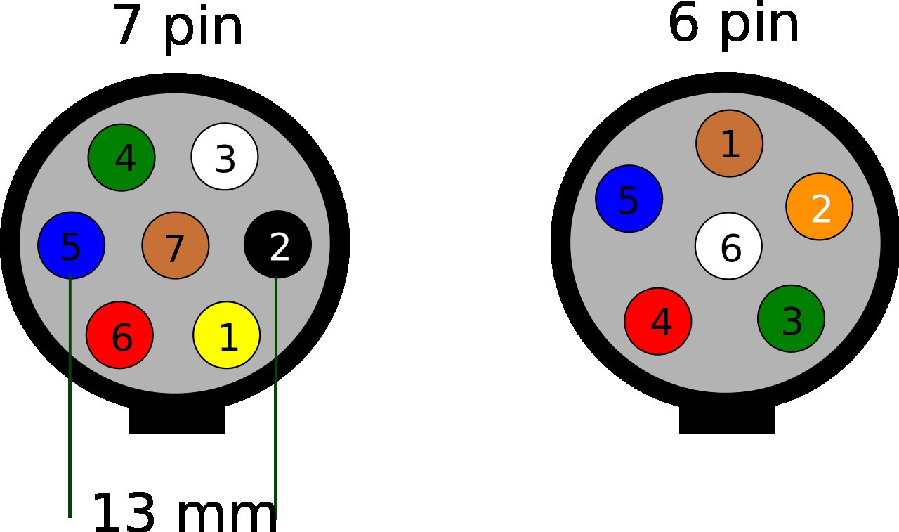
6 Pin Trailer Connector Wiring Diagram Free Wiring Diagram
In this video, I cover pitfalls to avoid when wiring your trailer lights, including:- differences in RVIA/NFPA1192 and SAE J2803 color codes- color code and.
Standard Trailer Wiring Diagram
Wiring Diagram for 7-Way Round Pin Trailer and Vehicle Side Connectors Question: wiring pollak j560jun93 to 7pin round narva truck to trailer thank. asked by: Michael Expert Reply: I have added a photo detailing the wiring connections for the Pollack Heavy-Duty, 7-Pole, Round Pin conncetor, # PK11700, see link.
7 Pin Connector Wiring Diagram Wiring Diagram
The 7 pin round trailer plug diagram is divided into two sections: the power side and the ground side. On the power side, there are five terminals that provide the power for the trailer. These include left turn signal, right turn signal, running lights, brake lights, and ground.

7 Pin Rv Wiring
Various connectors are available from four to seven pins that allow for the transfer of power for the lighting as well as auxiliary functions such as an electric trailer brake controller, backup lights, or a 12V power supply for a winch or interior trailer lights.
7 pin trailer connector wire diagram inrikoeng
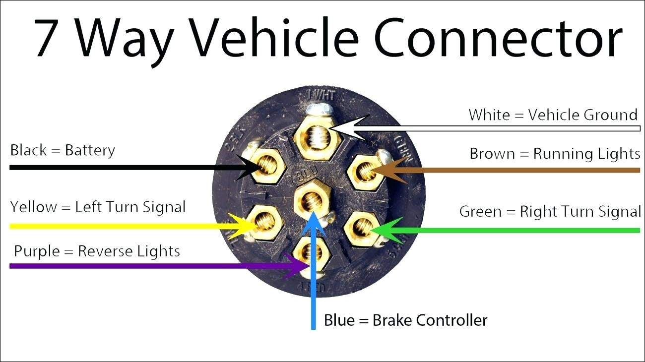
The center pin is usually for the yellow wire but it is the AUX pin that could power just about anything. Usually, it is the trailer's back up lights. This is okay if your state does not require that your trailer have back up lights. The way the 7-pin is marked is as follows- 1 White = Ground. 2 Blue = Brake.
What Is The Difference Between And 13 Pin Connectors? Adapter For 13pin To 7pin Trailer
7 Way Plug Wiring Diagram Standard Wiring* This is the most common (Standard) wiring scheme for RV Plugs and the one used by major auto manufacturers today. * Always test wires for function and wire accordingly. This wiring scheme is for reference only. copyright © 2001, Country Trailer Sales All Rights Reserved

7 Way Trailer Connector Wiring
The minimum suggested wire size for a 7-way trailer plug is 16 gauge for the turn signals, brake lights, reverse lights, and running light wires. The suggested minimum for the ground, brake power, and battery hot lead wires is 12 gauge. Shop Custom Wiring Wiring a Trailer with a 7-Way: Step by Step
Wiring For 7 Pin Trailer Plug
Understanding the wiring diagram is essential for anyone looking to install a 7-pin trailer plug. Each pin represents a specific function, such as tail lights, brake lights, or turn signals. By following the wiring diagram, you can easily connect the corresponding wires from your vehicle's electrical system to the trailer plug.

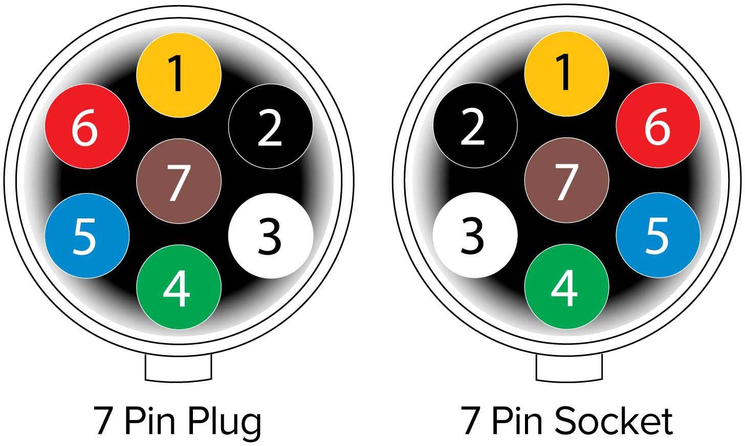
Wiring Diagram For 7 Pin Trailer Socket
Watch on Two Types of Custom Wiring Custom Wiring Harnesses A custom wiring harness has multiple plugs that are used to 'T' into the vehicle's taillight assembly, drawing power directly from the taillights or from a direct battery connection and providing a standard trailer light wiring connector.

39 Reese 7 Pin Wiring Diagram Wiring Diagram Online Source
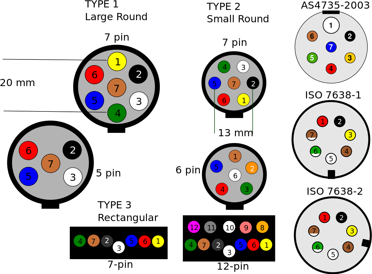
All diagrams are as viewed from the Cable Side Small 7 Pin Round (QLD) Identifying: Plug size is similar to an Australian 10c coin. There is a noticeably larger gap between 1 and 6 on this plug, though some trailer places rotate this connector that the yellow is at the top. Socket and plug are keyed. All diagrams are as viewed from the Cable Side
7 pin rv plug diagram Wiring Diagram and Schematics
The 7-Way Trailer Plug is around 2″ diameter connector that allows an additional pin for an auxiliary 12-volt power or backup lights. It is usually used for towing heavy-duty cargo trailers, aluminum trailers, dump trailers, utility / landscape trailers, equipment trailers, open car haulers and enclosed car haulers.